Cart is empty

How to Make a Category 5 or Cat 5E Patch Cable
Special Price LKR 0.00
Regular Price:

How to Make a Category 5 / Cat 5E Patch Cable
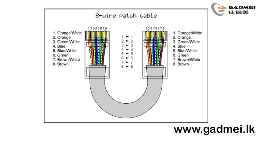
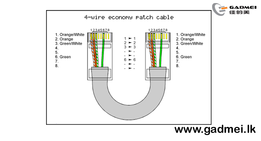
Before you begin, you should know which wiring scheme you will be using. The only difference between 568A and 568B wiring is that pairs 2 and 3 (orange and green) are swapped. If you are unsure which one to use then you should go with the 568B diagram. It is the 568B diagram that we demonstrate in this tutorial and the 568A wiring is shown in the diagrams below mainly for illustration. In our estimation the 568B connection is used in over 99% of all straight through applications. Know that using either the A or B standard will produce a "straight through" connection that should work for any Ethernet or POE (power over Ethernet) application. Therefore do not sweat over the choice.
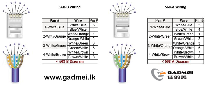
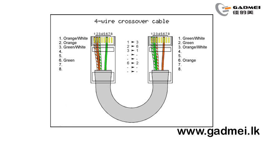
Application Note: To make a crossover patch cable, you should wire one end 568B and the other end 568A
How to make a Cat 5 or Cat 6 Patch Cable: Install RJ-45 Connectors: Easy Loadbar Method
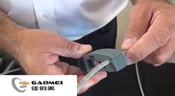
1) Start at about 1.5" to 2" back on the cable and skin the cable's jacket. Circle the cable with the tool 1-2 times.

2) Remove the stripper tool and gently bend the cable where it was scored by the tool in both directions (back and forth). The cable's outer jacket should just pull off.
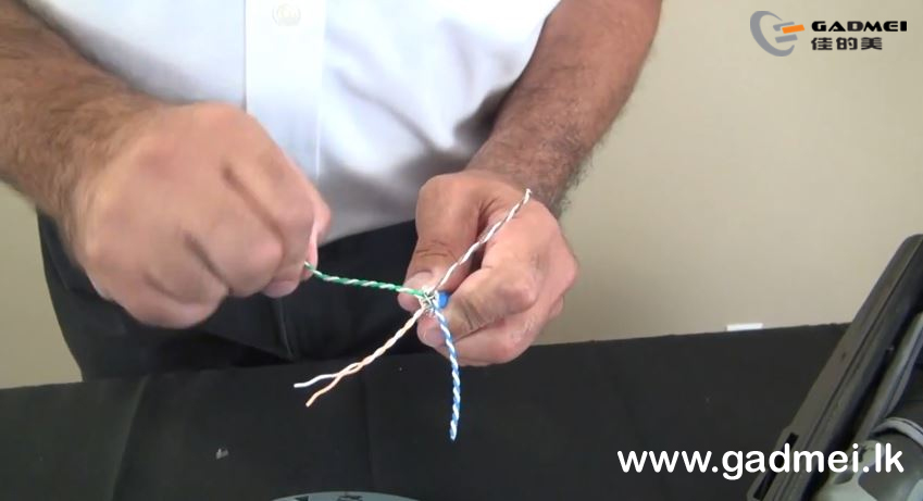
3) Begin to untwist each pair
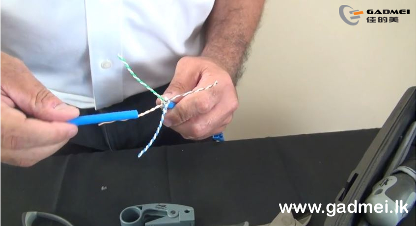
4) Use the discarded piece of the cable's jacket to complete the process. Leave about 1 twist at the end.

5) Straighten out the wires. Use of a blunt edge tool like a long nose pliers will help greatly and save your fingers.
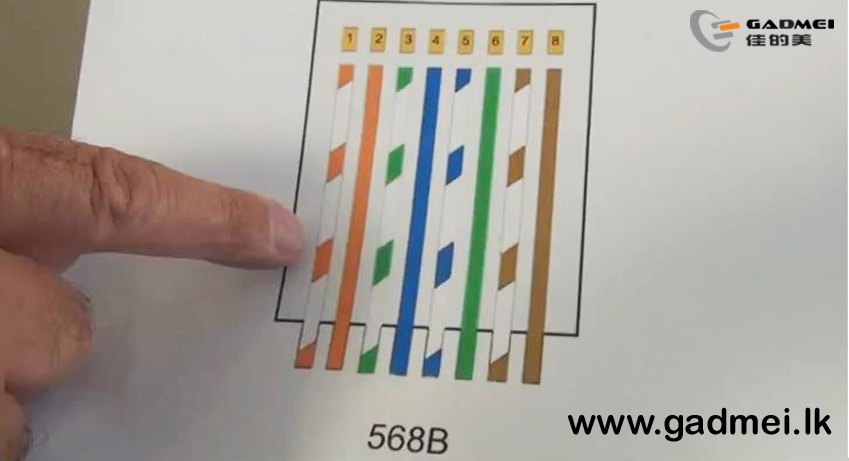
6) Refer to the diagram that you intend to use. In this case, we are using the 568B scheme.
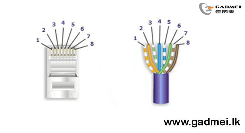

7) Put the wires in the appropriate order and get them as straight and close together as possible by running them through your fingers

8) While holding the group of wires in perfect fashion, cut off about 0.25" from the end to get the wires ready to go into the loadbar.
Tip:Be sure to hold the wires tightly or you may have to do the process all over.
Tip:We strongly recommend using a sharp pair of "Electricians Scissors" to make the cuts. Using a cutting plier can flatten the ends making it impossible to get the wires into the holes of the loadbar.

9) Insert the wires into the loadbar with the hollow end of the loadbar facing the wires. Slide the loadbar down on the wires
Tip:Gently jiggle the wires from side to side while maintaining pressure on the bundle and they will all come through easily.
Tip:Check the sequence of the colors once again before you proceed to the next step.
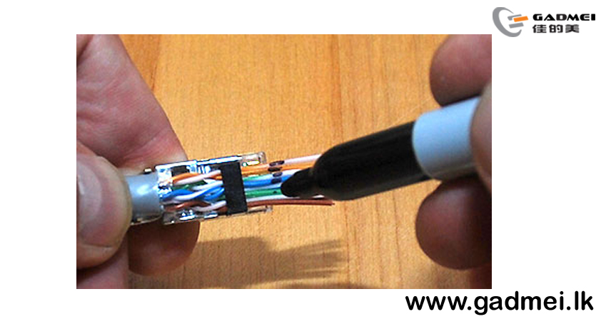
10) Put the wire assembly over a connector so that the jacket is about 1/8" into the connector. Then mark the wire at the point where it is even with the end of the connector.

11) Use the electrician's wire scissors to cut the wires straight across at the point where you made the mark.
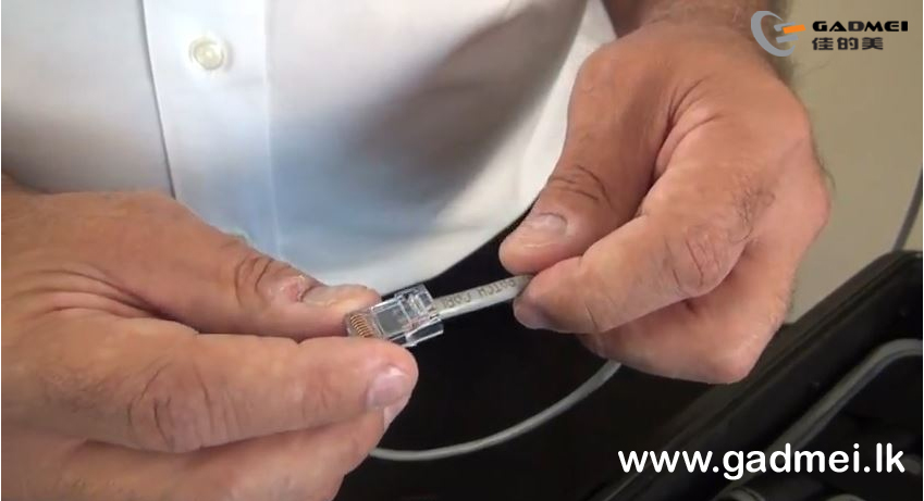
12) With the Orange pair furthest away from you and the Brown pair closest, slide the connector on to the assembly with the pins facing up and the locking clip facing down. Push the assembly into the connector with a slight wiggling motion to make the ends of the wires go all the way to the end of the connector. It may be necessary to use moderately firm pushing to make this happen. At this point it is advisable to use a magnifying glass or jeweler's loop to look directly into the face of the connector to see that the wires have gone all the way in.

13) Insert the connector into the crimper and keep pressure on the cable (pushing it in to the connector) until the crimp is complete. Use a high quality Industry Standard Crimper such as our QuickTreX® Professional "Five In One" Modular Crimping Tool

14) If you intend to use cable boots, slide them onto the cable now before installing the opposite connector. Boots are completely optional.
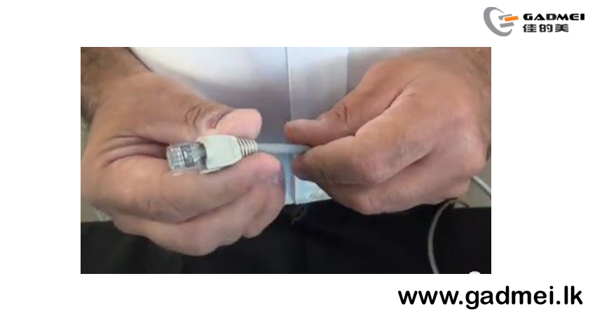
15) Repeat the process and install the connector on the opposite end.
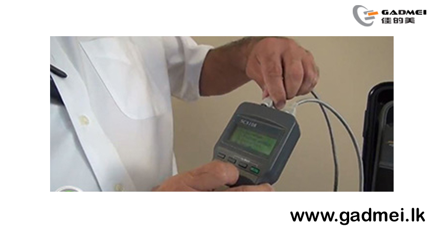
16) Test the cable with a 4-pair type Cable Tester.
Thank you for visiting - gadmei.lk
For your Inquiries
Message or Call us @ 071-5394567/ 0721398433
Website: www.gadmei.lk
GADMEI COMPUTER TECNOLOGY
SHOWROOM
250 2ND FLOOR JJ CITY NAWALA ROAD RAJAGIRYA
Email : info@gadmei.lk/ gadmeisrilanka@gmail.com
Landline: +94 115 530230
LAPTOP MOTHERBOARD REPAIR CENTER
NO 219 2ND FLOOR JJ CITY NAWALA ROAD RAJAGIRIYA
Landline: +94 115 518727