
Cart is empty
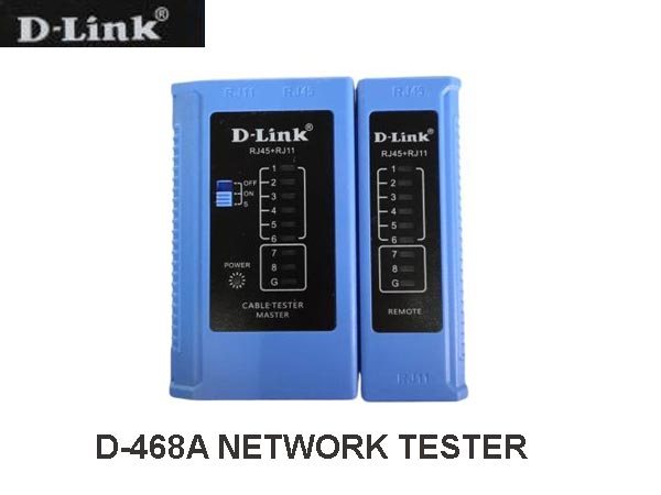

NETWORK SWITCH D-LINK
Special Price LKR 2500.00
Regular Price:
- Islandwide Delivery Available
The D-Link 468A is a handheld remote network cable tester widely sold under model code DL-468A or similar generic 468-series designations (frequently referenced alongside the generic NS-468 or NSS-468A layout).
It is designed to troubleshoot twisted-pair data and voice lines.
- Cable Types: Tests RJ45 (Cat5, Cat5e, Cat6, UTP) and RJ11/RJ12 (telephone) wires.
- Fault Detection: Checks for continuity, open circuits, short circuits, and crossed/miswired pairs.
- Display: Uses sequential LED indicator lights on both the main and detachable remote units.
- Power: Operates using a single standard 9V battery
-
Detachable Remote Tester: Allows field testing of long-distance structured cabling runs pre-terminated inside wall plates, patch panels, or ceiling drops.
-
Automatic LED Scanning: Sequentially pulses power pin-by-pin across wires 1 through 8 and Shield (G) to visually highlight incorrect wiring or broken conductors.
-
Crossover & Straight-Through Verification: Instantly identifies whether an Ethernet patch cord is wired according to T568A, T568B, or crossover configurations.
-
Shielding Test: Dedicated LED indicator labeled G to confirm ground continuity on shielded Twisted Pair (STP/FTP) cables
Model: D-Link D-468A (DL-468A)
Compatible Cable Types: UTP/STP/FTP Twisted Pair Cables, RJ45 Ethernet, RJ11/RJ12 Telephone Lines
Supported Ethernet Categories: Cat3, Cat5, Cat5e, Cat6, Cat6A
Connector Interfaces: RJ45 (8P8C), RJ11 (6P4C / 6P2C), RJ12 (6P6C)
Testing Architecture: Detachable Master Unit and Remote Terminator Unit (for installed run testing)
Fault Detection Capability: Continuity, Open Circuits, Short Circuits, Cross-connections, Split Pairs, Shielding Ground G.
Display / Indicator 9-LED Status Array on Master & Remote Units (Pins 1–8 + Ground/Shield)
Operating Modes
ON: Normal/Fast Scanning
S: Slow Scanning (for precise pin-by-pin observation)
OFF: Power Off
Power SupplyStandard 9V DC Layered Battery / PP3 (NEDA 1604 / 6F22)
Power Consumption Approx. 25 mA operating current Enclosure
Material: High-impact ABS Plastic
Dimensions (L × W × H) Approx. 104 mm × 96 mm × 27 mm Weight ~125 g to 150 g (excluding battery)
Diagnostic LED Matrix Standard
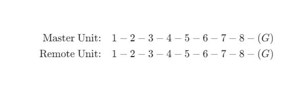
When testing a healthy straight-through (T568A or T568B) Ethernet cable, both units cycle through simultaneously:
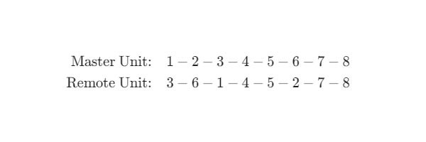
For a standard crossover cable, the sequence displays as follows:
The 468 / NS-468 / DL-468A Network Cable Tester is a hardware continuity tester used for testing RJ45 (Ethernet Cat5/Cat5e/Cat6) and RJ11/RJ12 (telephone) twisted-pair cables.
It requires no software configuration or network setup; operation is driven by hardware continuity scanning.
1. Setup & Preparation
-
Power Supply: Install a standard 9V battery into the rear battery compartment of the master unit. The remote unit does not require a battery as it draws power through the cable loop.
-
Connecting Cables:
-
For patch cords: Plug one end into the master unit's RJ45 (or RJ11) port and the other end into the remote unit.
-
For installed structured cabling (wall jack to patch panel): Slide the remote unit off the master main unit, plug one end into the wall jack, and plug the other end into the master unit at the patch panel.
-
⚠️ CRITICAL WARNING: Never plug the tester into a live network port (PoE, switch, router, or active phone line). Voltages from energized lines will permanently fry the tester's internal circuits.
2. Operation Modes
Slide the three-position power switch on the master unit:
-
OFF: Powers down the tester.
-
ON (Fast Scan): Cycles through pins 1–8 and G (Ground/Shield) rapidly.
-
S (Slow Scan): Cycles through pins sequentially at a slower speed, making it much easier to trace miswires and individual pin faults visually.
3. Interpreting LED Test Results
When turned ON, the master unit fires pulses from Pin 1 through Pin 8 (and G for shielded cables) in sequence. Compare the sequence on both units to diagnose the cable:
1. Straight-Through Cable (T568A or T568B Standard)
Both units light up sequentially in identical order:
-
Master:
1 - 2 - 3 - 4 - 5 - 6 - 7 - 8 - (G) -
Remote:
1 - 2 - 3 - 4 - 5 - 6 - 7 - 8 - (G)
2. Crossover Cable
If testing a standard Gigabit/Fast Ethernet crossover cable:
-
Master:
1 - 2 - 3 - 4 - 5 - 6 - 7 - 8 -
Remote:
3 - 6 - 1 - 4 - 5 - 2 - 7 - 8
4. Diagnosing Common Faults
| Fault Type | LED Behavior | Cause & Solution |
| Open Circuit (Broken Wire) | A pin number (e.g., Pin 3) fails to light up on either the Master or Remote unit. | The wire inside is cut, or the crimping pin on the RJ45 plug failed to pierce the insulation. Re-crimp new ends. |
| Short Circuit | Multiple LEDs light up simultaneously or remain dimly lit when a single pin is triggered. | Bare wires inside the plug or jacket are touching. |
| Miswire / Wrong Sequence | The Remote unit lights up out of order (e.g., Master reads 1-2-3-4, Remote reads 1-3-2-4). |
The color code sequence was mixed up during crimping/punch down. Cut off connectors and re-terminate using the T568B order. |
| Shield / Ground Fault | The G LED fails to light up on shielded (STP/FTP) cables. | The drain wire or metal RJ45 collar is not grounding properly. |
Quick Reference: T568B Standard Wiring
If you need to re-crimp a damaged RJ45 end, align the wires left-to-right (clip facing away):
-
White/Orange
-
Orange
-
White/Green
-
Blue
-
White/Blue
-
Green
-
White/Brown
-
Brown
The D-Link DL-468A is a compact, dual-unit electronic cable tester designed to verify line continuity, pin assignments, and wiring faults on network (Ethernet) and telecommunication cables prior to or post-installation.