
Cart is empty
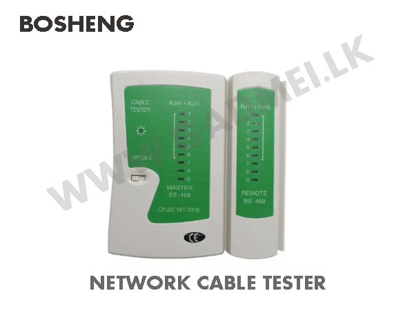


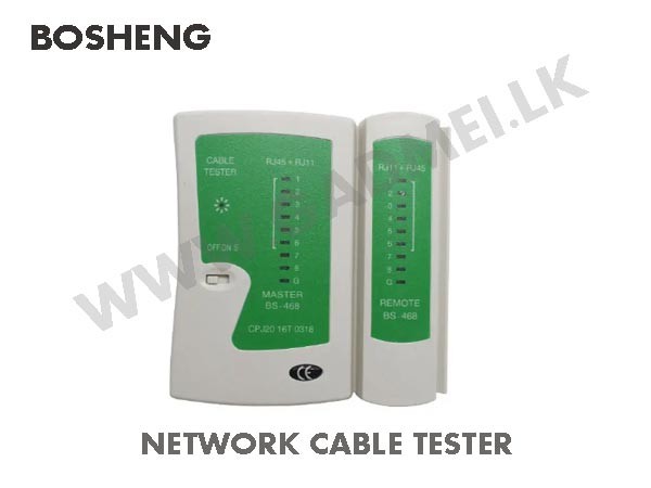
TOOL Network Cable Tester RJ45 and RJ11
Special Price LKR 1300.00
Regular Price:
- Islandwide Delivery Available
The Bosheng BS-468 is a portable, two-unit diagnostic tool designed to test RJ45 Ethernet and RJ11/RJ12 telephone cables. It quickly identifies wiring faults like open circuits, short circuits, crossed wires, and miswirings using clear LED indicators.
- Dual Ports: Supports RJ45 (8P8C) for LAN cables and RJ11/RJ12 (6P4C/6P2C) for phone lines.
- Master and Remote Units: Splits into two connected or separate parts to test cables across rooms or long pre-installed wall runs.
- LED Status Lights: Features 9 indicator lights (1 through 8 for core wires and G for ground/shield) to map out pin-by-pin continuity.
- Testing Modes: Includes a 3-position power switch on the master unit for OFF, normal test speed (ON), and slow test speed (S).
- Power Supply: Powered by a single standard 9V battery.
- Dual Ports: Supports RJ45 (8P8C) for LAN cables and RJ11/RJ12 (6P4C/6P2C) for phone lines.
- Master and Remote Units: Splits into two connected or separate parts to test cables across rooms or long pre-installed wall runs.
- LED Status Lights: Features 9 indicator lights (1 through 8 for core wires and G for ground/shield) to map out pin-by-pin continuity.
- Testing Modes: Includes a 3-position power switch on the master unit for OFF, normal test speed (ON), and slow test speed (S).
- Power Supply: Powered by a single standard 9V battery.
Standard connection diagram for the BS-468 network cable tester:
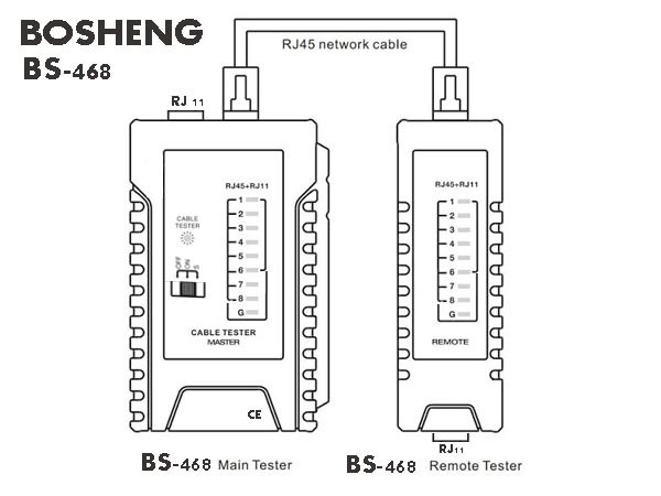
To connect and use the Bosheng BS-468 network cable tester, plug one end of the cable into the master unit and the opposite end into the remote unit, turn the power switch to "ON" or "S," and check that the LED lights match sequentially from 1 to 8 on both sides.
More details:
-
Plug One End into the Master Unit: Insert one RJ45 (or RJ11) connector into the top jack of the main tester unit.
-
Plug the Other End into the Remote Unit: Insert the opposite end of the cable into the top jack of the remote unit. (If testing patch cords at a workbench, you can slide the remote unit into the side track of the main unit).
-
Power On: Slide the switch on the main unit from OFF to ON (for normal speed) or S (slow scan mode, which makes checking LED sequences easier).
How to Read the LED Indicators
-
Straight-Through Cable (Normal Patch Lead):
-
Main:
1 - 2 - 3 - 4 - 5 - 6 - 7 - 8 - G -
Remote:
1 - 2 - 3 - 4 - 5 - 6 - 7 - 8 - G(Lights flash sequentially in sync on both units).
-
-
Crossover Cable (T568A to T568B):
-
Main:
1 - 2 - 3 - 4 - 5 - 6 - 7 - 8 - G -
Remote:
3 - 6 - 1 - 4 - 5 - 2 - 7 - 8 - G
-
-
Fault Signals:
-
Open Circuit / Broken Wire: If a pin (e.g., pin 3) is disconnected, LED 3 will not light up on either the main or remote unit.
-
Short Circuit: Multiple LEDs will flash simultaneously or dimly.
-
Miswire: LEDs will flash out of numerical sequence on the remote unit.
-
(Note: The G light indicates shield grounding for shielded STP/FTP cables; it will remain unlit for unshielded UTP cables.)
The Bosheng BS-468 is a portable diagnostic tool widely used to test network and telephone cables.
-
Primary Function: Diagnostics tool used to quickly test RJ45 (Cat5/6 Ethernet) and RJ11/12 (telephone) cables for open circuits, shorts, and miswires.
-
Core Components: Consists of a main master unit and a detachable remote unit to check pre-installed wall cables or long wire runs across rooms.
-
Key Features:
-
Dual-speed switch (ON for normal speed, S for slow scan).
-
1–8 LED sequential lights (plus G for shielded cables) for clear pin-by-pin readings.
-
-
Ideal for: network technicians, IT professionals, and DIY hardware setups.